When bringing up a new hardware product and testing its functionality, you really start to get to know the “personality” of the hardware, including some of the unexpected bugs that come along with new hardware. Such is the case with my new uBMS board and the ESP32 driving the whole project.
The background
The other day, I set about finally testing out the balancing functionality of my board,in order to confirm that it works, and to collect data to allow me to estimate my current draw for a given PWM duty cycle. That way I could save on sensors, but also have reasonably accurate current measurements for each cell being balanced. This meant that for varying duty cycles, until I reached my current limit, I began collecting data of current for a given duty cycle. The funny thing I started to notice when I was collecting my data, however, is an error that would present itself as:rst:0x8 (TG1WDT_SYS_RESET),boot:0x13
…and then my ESP would then promptly reset.
Troubleshooting
This is always the fun part of designing and working with a new product: encountering and then promptly having to fix all the unexpected errors that living in the “real world” presents itself with. Here, I had to fix this reset error. Having a BMS that constantly resets during balancing of its cells is an inconvenience, but is also a major safety hazard to the user.
I’ve encountered a similar error to the one above when developing for the ESP32. Usually, when a microcontroller such as the ESP32 throws a watchdog error, which is basically what the WDT in TG1WDT stands for, your code is to blame. Usually, your code is running a tight loop and the RTOS is unable to alert the watchdog and so when too much time passes, the watchdog gets upset, and then promptly resets your micro. At first I thought that is what was happening to me too, but I couldn’t understand what about my simple test code would cause such a watchdog timer problem. That’s where I knew I would have to dig deeper…
Looking for patterns
Whenever encountering an issue that you are not familiar with, or do not know what is causing said issue, I find it best to look for patterns surrounding the issue. The more patterns you can find the more clues you can obtain as to what the root cause of your issue is, and then how to fix it.
- What is my code doing when the problem seems to occur? - Here I was giving my code a duty cycle to set its PWM output to and then I would monitor the current draw from my power supply
- What are the patterns of failure? - I started to notice that oddly, at lower duty cycles I would have the ESP32 crash with this watchdog timer error, occasionally at higher duty cycles, but mostly the lower the more often it would crash. I also noticed that the failure only happened when the power supply was on. When changing the duty cycle with the power supply off, there was no effect.
- Is there a reason why this pattern might obviously cause this failure mode? - I couldn’t think about why changing my duty cycle would throw a watch dog timer error, and this really had me stumped for awhile
Test Fixture
Since I couldn’t deduce why this noticed pattern of failure would cause a watch dog timer, I made a similar test fixture where I could more easily measure parameters surrounding the working mechanism. This included the main components of my balancing architecture:
- An ESP32 dev board, using the same PWM pin
- A high-pass filter on the input to the gate of the MOSFET utilising the same values on my board
- A slightly different, but similarly capable power MOSFET
- The same exact code and PWM duty cycles
What was funny about testing with this fixture is that I noticed no resetting of the ESP32, no matter the duty cycle of length at which I let it run.
Probing
Since I knew the issue occurred with my PWM pin and when my power supply was on, I added my oscilloscope probes around those important points: The PWM pin on the ESP32, the MOSFET’s Gate, the MOSFET’s Drain.
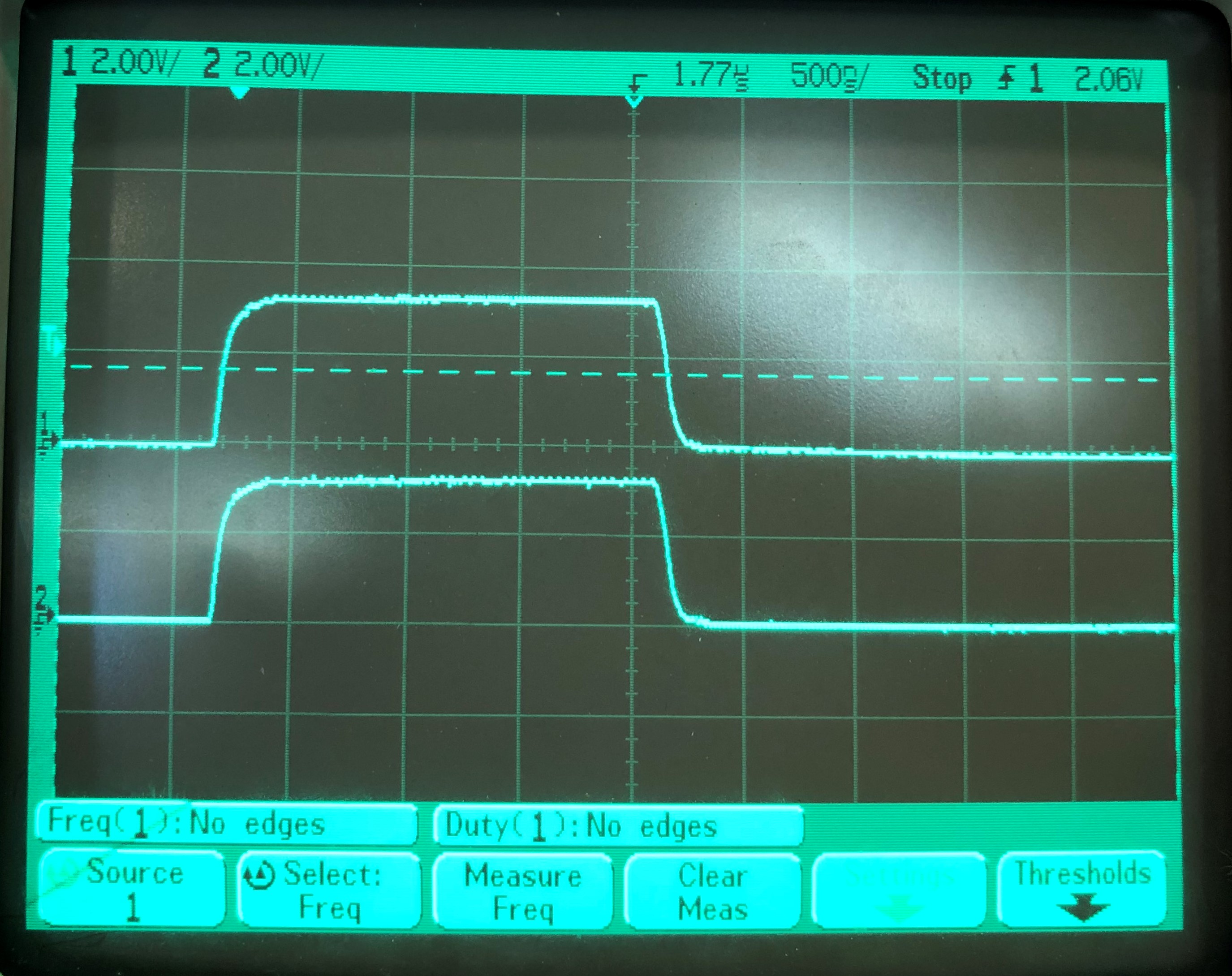
These are the resulting waveforms that I got:
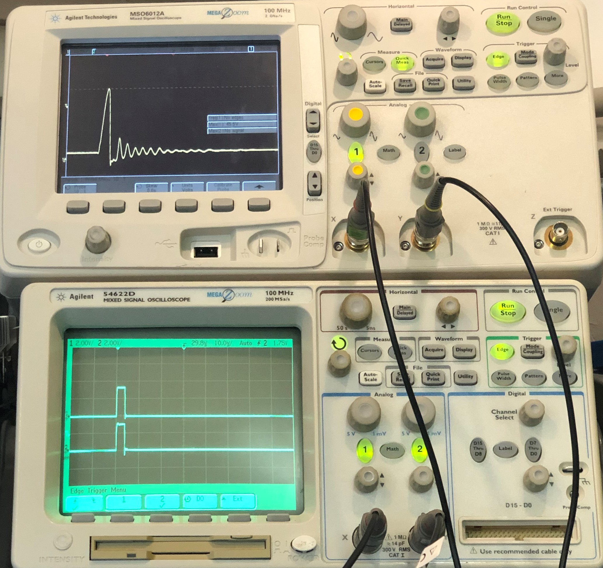
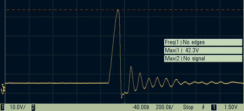
The PWM signals looked okay, but the voltage spikes on the drain worried me, not just for the transistor, but in general one should try to avoid 10x voltage spikes. I also witnessed this tiny voltage spike on the PWM signal (going below ground on the falling edge) go on and off as I switched the power supply on and off. There I realised that my high voltage spike on the drain was managing to couple its way back to the ESP32’s PWM pin… not ideal. Therefore, I thought about where this initial voltage spike was coming from and realised it must be coming from the inductance created by the leads leading into the BMS, the relatively high balance current, and the very quick switching time of my MOSFET.
You can see the effect with my roughly drawn diagram of a simple wire conductor and some relevant equations…
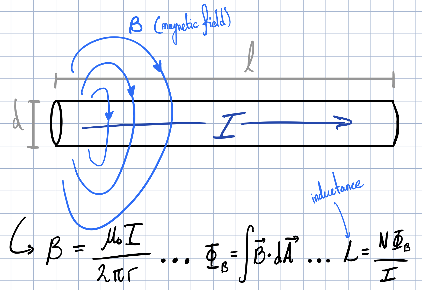
but overall, the most important equation, given by Faraday’s law on induction, is this one: V = -L*(dI/dt) and what is important here is that: 1. The minus sign in front of the inductance and 2. the fact that dI/dt can be negative. Considering that the MOSFET I am using has a worst case turn-off fall time of just 110ns, any little inductance from the leads becomes significant. That’s where the large inductive spike on the drain of the MOSFET comes from, it comes from when when the transistor turns off so suddenly… and the subsequent ringing is caused by many parasitic capacitances that forms a LC-tank oscillator.
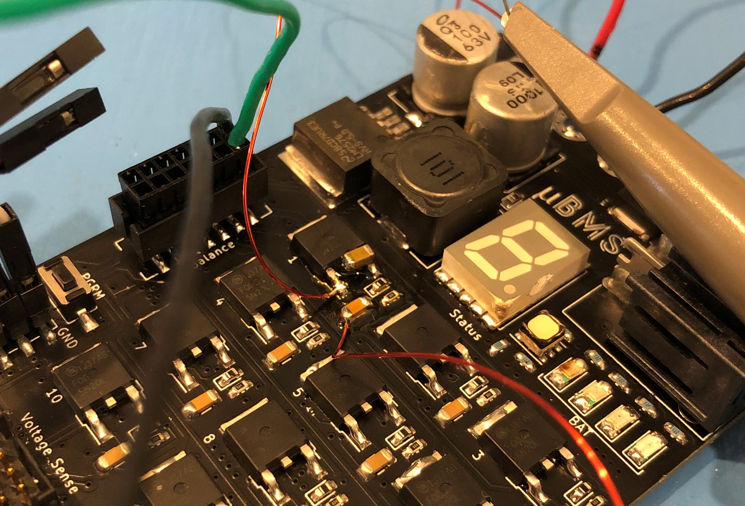
Nonetheless, if you consider the world of complex numbers there is not only resistance, but an imaginary part called reactance. What’s cool about using this form to think about inductance and capacitance (which both fall into ‘reactance’), is that it becomes easier to ‘cancel’ them out. Capacitance has a negative reactance and inductance has a positive reactance, so, in theory, we can help to cancel out the lead inductance, and therefore the inductive spiking, with some added capacitance near the affected gate. I tested this theory with my test fixture and it proved to work well and reduced the spiking by about 3x with a random value electrolytic capacitor I took out of my drawer.
Conclusion
Ultimately, the addition of this small 1206 capacitor provided enough negative reactance on the Drain of the MOSFET so that the voltage spike was reduced by several fold, and no noticeable spikes were coupled back to the gate and then back to the PWM pin on the ESP32.
This led to stability for the ESP32 and its generation of the PWM signal and for the balance circuitry. What started out as quest to solve a software bug quickly led itself to a hardware one where some basic circuit knowledge led to a somewhat elegant, simple, and cheap solution. So, if you ever have a bug that you think is software related, but reacts to physical inputs, check your hardware again! You might be surprised what you find…