The Timeline
- Saturday: DigiKey Parts
- After failing to deliver on Friday due to undetermined reasons, I adventured up to Albany, NY and waited for a couple of hours for the kind FedEx employees to locate and give me my package so I was able to start soldering this weekend
- Sunday: Soldering Starts
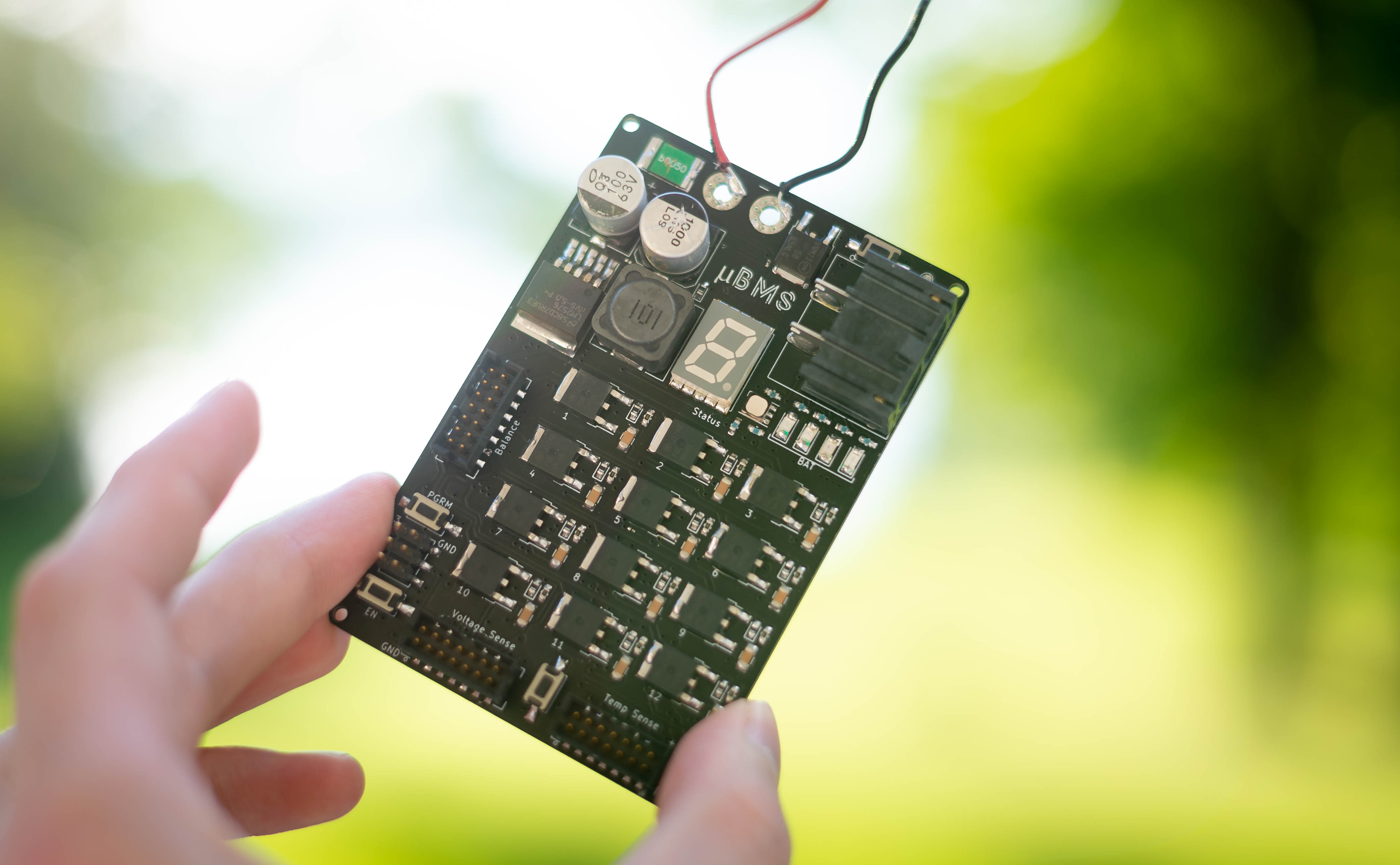
- The real fun began today. I got the main power rails of the μBMS working first. There are 2 main rails on the μBMS: a 5V rail from a high-voltage tolerant buck-converter and a 3.3v rail from an LDO attached to the 5v rail. This caused some issues to begin with, but more on that later…
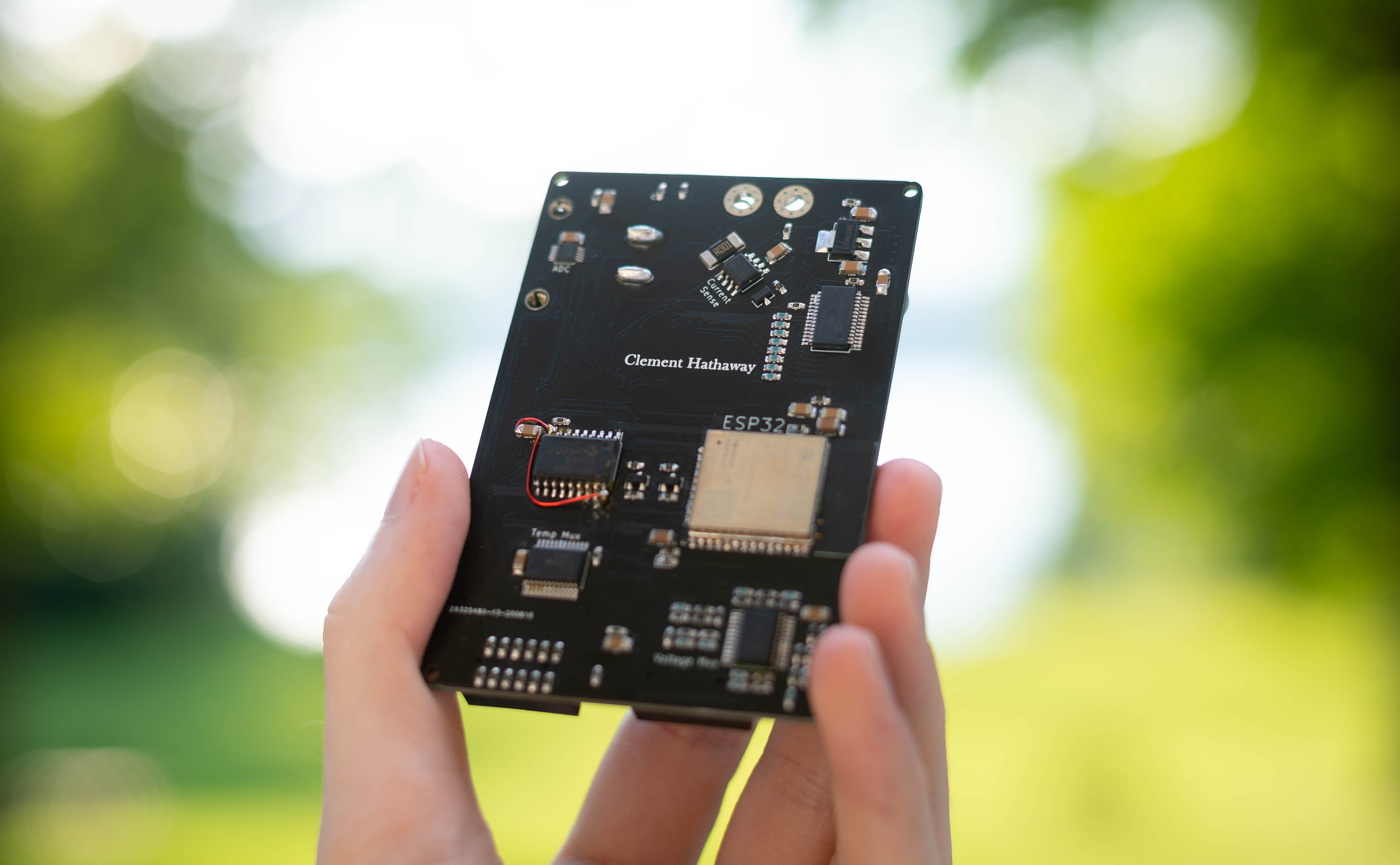
- After confirming I had my required power rails, I worked on inserting the brain into μBMS. The chip making up its brain is an ESP32 and after attaching this module and surrounding programming circuitry I was ready for my first test: UART communication with the “Hello World” programme. Luckily, the μBMS has a functioning brain, but still has some weird quirks booting up… more on this later
- Monday: Stress!… but then Exciting Results
- Today was a super busy day! I set the goal of completing all of the soldering for all of the parts. There are about 200 parts on the board and I still had about 150 more to do. This went fairly smoothly until I ran into my 1 board design flaw (I’m sure I’ll find more 😅).
- I made a pinout error on an IC and ran around with red herrings with my 5v rail was shorted until I had the foresight to do a “Louis Rossmann” and use a current limited supply and a temp probe to find the offending location / parts on the board. It’s fixed now, and the chip seems to have survived the abuse
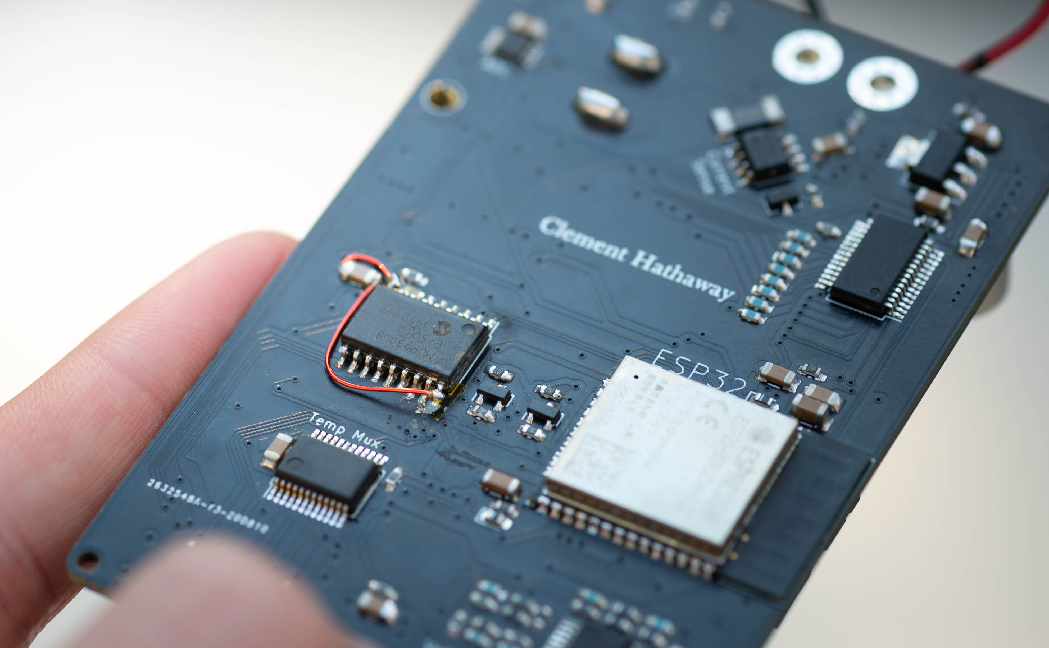
- Anyway, I managed to finish the board, even with 3 0201 thermistors, at around 7pm and now we’re here, onto testing and firmware, but first more about μBMS and why it’s the coolest project I’ve ever embarked on…
So why is μBMS cool?
μBMS is what I believe a proper hobbyist battery management solution looks like. It combines all the features I have ever wanted in a BMS for my electric vehicle projects into one compact but complex 4-layer board. It will be the future BMS for all my electric vehicle projects. To get here, however, I first made a set of requirements I felt to be essential to this project.
- Be Powerful - Most generic BMS solutions for hobbyists just sense a voltage and turn on a balancing MOSFET, I wanted μBMS to do more. It supports:
- 12-cell voltage monitoring, each with dedicated sense leads
- 12-cell passive balancing, each with adjustable current
- 12-cell temperature monitoring with high resolution
- Be Affordable - μBMS needed to also be as affordable as possible. There are fancy BMSs out there, but they also cost hundreds of dollars. I want μBMS to be easily under the $100 mark so it is obtainable for hobbyists
- Be Simple (to use) - There are a couple of more “smart” and relatively affordable BMS options out there, but their control interfaces are complex and require you to download an app on either your phone or your computer. μBMS will use a standard Web App approach where all you need to do is visit a website on whatever internet connected device you want!
- Be Safe - Lithium-ion batteries are not the safest battery technology around, and require special attention to keep them within safe bounds. μBMS will prioritise the safety of the battery and the user including a module disconnect switch to turn off failing batteries and temperature monitoring every cell to capture failure signs early, before a fire might start.
- Be Modular - With increasingly big battery designs of small electric vehicles, it’s pretty common to have multiple battery “modules” for redundancy, extra capacity and ampacity. That’s why μBMS supports being one among many, so when I want to add these boards into my electric bicycle project, it’s ready to go.
So where am I at now?
I’m finally at the stage of development with the μBMS where I can properly begin working on Testing, Firmware Development, and Debugging. While it’s possible to start firmware development without the assembled PCB, and I have tested small features beforehand, having the actual hardware makes this process much easier.
I’ve already started on the firmware in pieces, and have outlined a rough flow chart for how I expect it to run on μBMS. Of course it’ll be more complex than this diagram shows, but it highlights some important and basic processes.
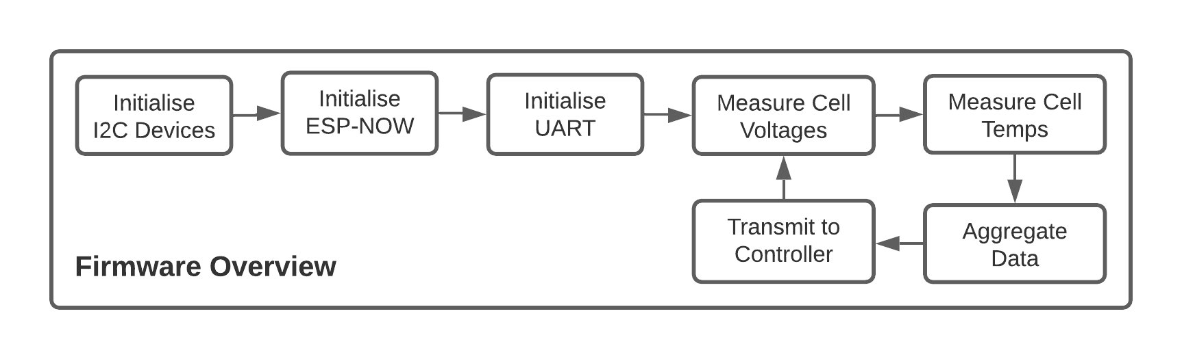
The majority of the code will be written within the Arduino environment, which, even if it is considered not as professional as other solutions like PlatformIO or the ESP-IDF, it is very functional, easy to use, and quite powerful when fully exploited. I plan to also keep the firmware public on Github so eventually other people can help contribute changes that they find useful :)
So, within the next week or so I hope to have a basic operational firmware up and running on the board and I will be giving another update here on the blog around then!
The Current Problems
- My PCB design isn’t perfect and the MCP23008 that I use for controlling my analogue multiplexers is currently shorted when soldered correctly on the board… I mistakenly switched Vss and Vdd on my schematic and failed to notice it beforehand. I learned that it’s very much worth it to spend 30 minutes checking over the design than to spend 4 hours debugging a dysfunctional board 😅. Luckily I could use most of my traces and only needed to lift two of the pins on the MCP23008 to get it working!
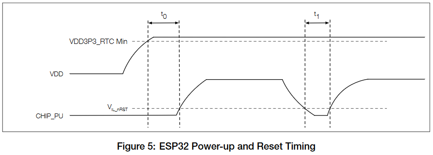
- The ESP32 start-up is currently not working correctly. The EN (enable) pin, also referenced in the datasheet as CHIP_PU requires to be set high with correct timing in according to the rising of the main 3.3v power rail. This is also an issue for disabling the chip when losing its main power rail, but I’m less worried about that here. Currently, once power is given to the ESP32 it puts the ESP32 in a unstable state where it does not function. The EN pin has to be cycled with a click of the EN button on the board to properly boot. I’m not entirely show how to fix the issue, or exactly where it lies… The datasheet provides this diagram for how it should be operated and I’m exploring how to satisfy these conditions.
- Power consumption is also another issue that will have to be sorted out with later revisions. It is pretty high for a battery operated device but I think I can fix this mostly with clever firmware… Stay tuned!
Encountered but Resolved Problems
- The pinout for Vin and GND being reversed on the MCP23008 which caused the 5v rail to be shorted to ground
- When first setting up the buck converter, in addition to being very unfamiliar with soldering large surface mount electrolytic capacitors, I mistakenly soldered the 0603 diode in the opposite orientation. This lead to the shorting of the 5v rail (again) and took me quite a good amount of time worrying that I had shorted out my main filter cap from the heat of my hot air station. Once I discovered the diode was the culprit, I replaced it with a fresh one since I had exceeded the rating of the diode and didn’t want to risk anymore issues :)
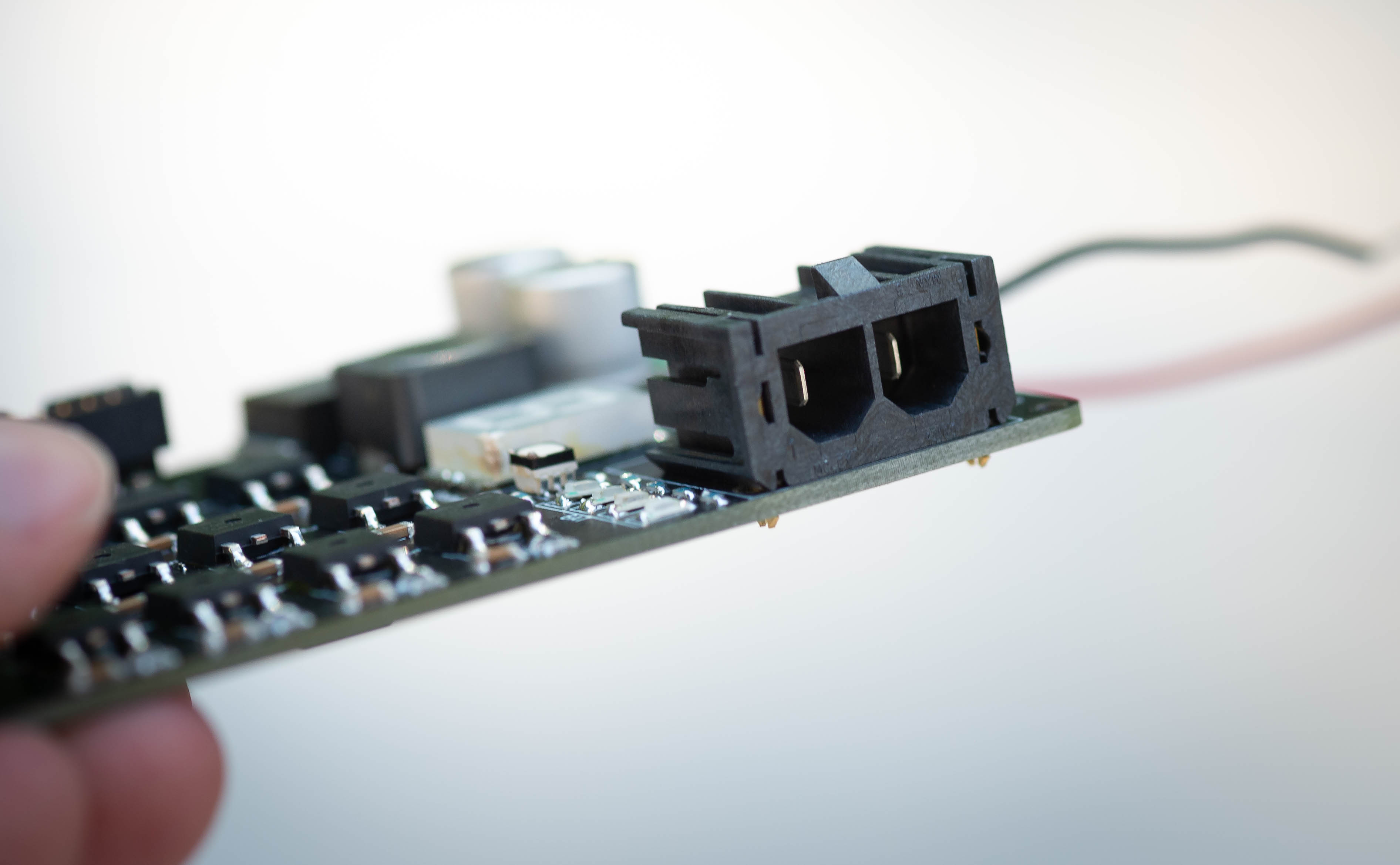
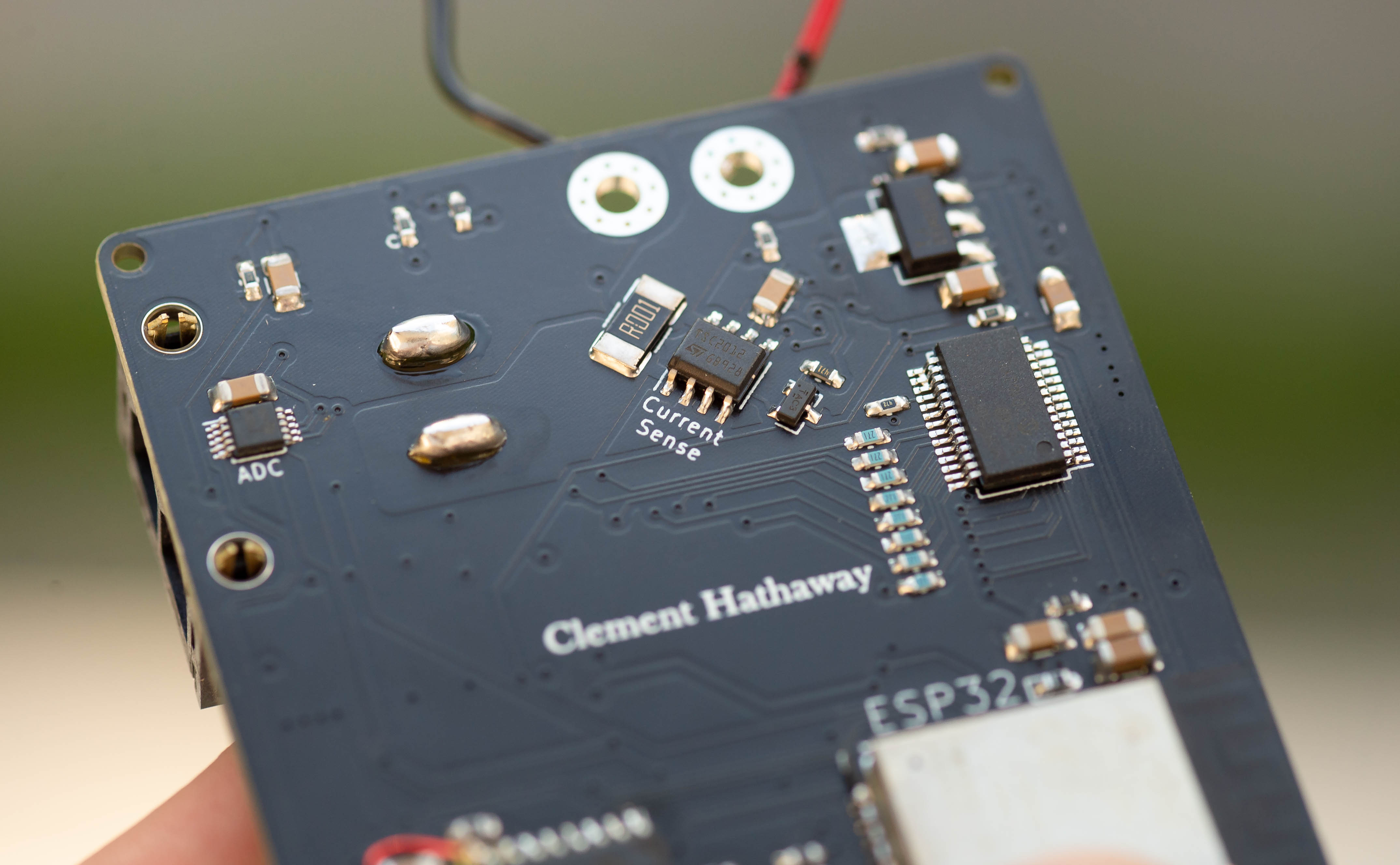
Some additional photos